Self-calibrating spatial intelligence for ceiling CCTV streams. Recovers 3D camera orientation,
un-tilts angled perspectives into 90-degree top-down coordinates, and overlays a discrete 0.5m x 0.5m metric grid
via human skeletal geometry.
Independent R&D Research: This prototype and mathematical framework was conceived, developed, and benchmarked by Timber Dang in an independent home-lab environment (using a mezzanine CCTV perspective). It demonstrates how high-angle surveillance cameras can automate spatial floor grid calibration without physical site measurements.
End-to-end execution of pipeline.py on the 95.4-second mezzanine camera recording.
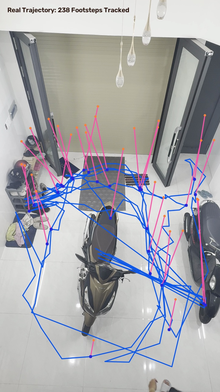
The pipeline extracted 238 high-confidence skeletal body vectors, solved the vertical vanishing point,
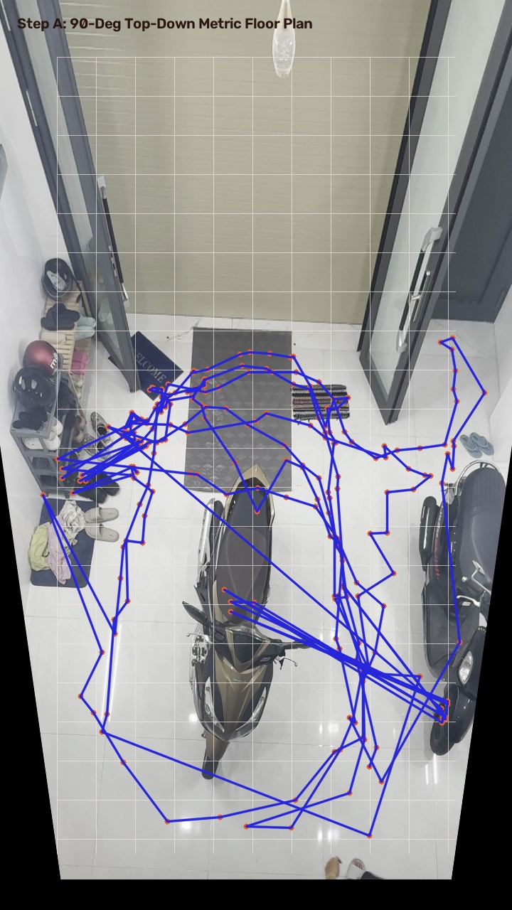
un-tilted the floor to 90 degrees, and mapped the walking trajectory across 0.5m x 0.5m metric zones.
Fig 1. Real Video • 238 Skeletal RulersAngled CCTV Feed
YOLO-Pose captures the head joint and foot contact point across frames. Purple rays show 3D upright human vectors acting as vertical physical rulers. Orange line shows the continuous transit path between the two vehicles.
Perspective distortion is mathematically removed. The floor is flattened into an aerial 90-degree bird's-eye coordinate system with an automated 0.5m x 0.5m metric grid. Red path maps true meter coordinates.
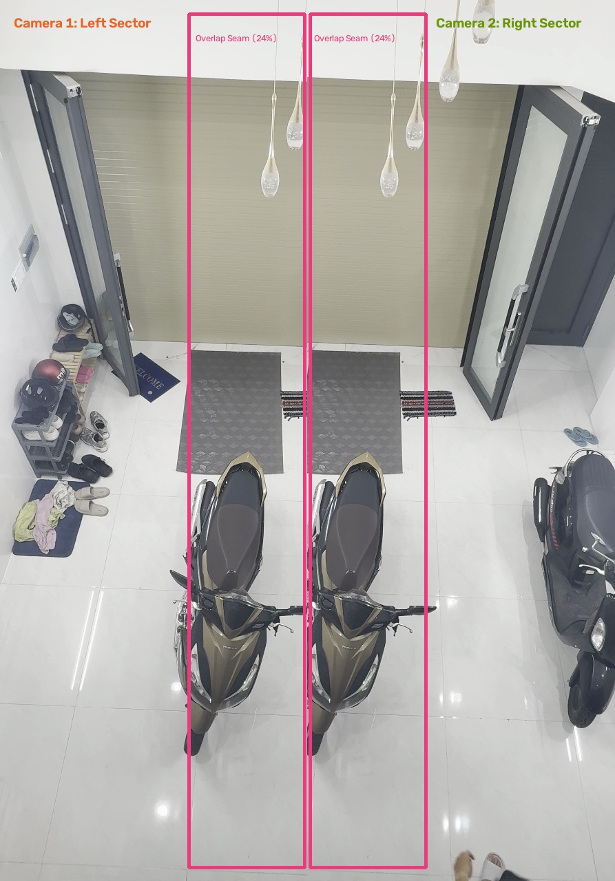
Fig 3. Step B • Multi-Camera Seam Stitching24% Overlap Corridor
Virtual multi-camera split: Camera 1 (Left Wing) and Camera 2 (Right Wing) share a 24% overlap seam corridor. Footstep coordinates matched across the seam corridor fuse adjacent cameras into a continuous mosaic.
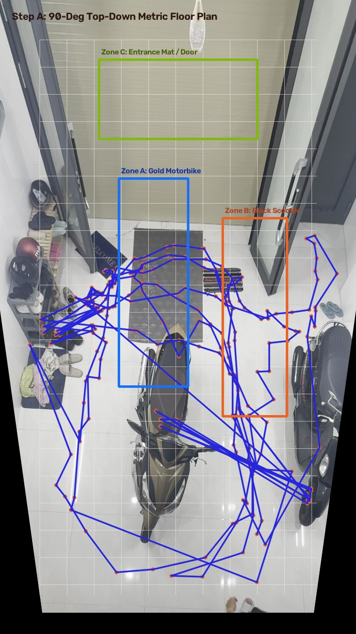
Fig 4. Step C • 0.5m Grid & Zone OccupancyFMS Point-in-Polygon
Operational zone polygons (Zone A: Gold Motorbike, Zone B: Black Scooter, Zone C: Entrance Mat). Foot coordinate queries evaluate occupancy in real time, incrementing headcount only when feet step inside zone boundaries.
1. Video Ingestion Sandbox & CCTV Emulation
Standard enterprise and industrial CCTV systems stream video feeds over RTSP/ONVIF protocols at Full HD (1080p) or HD (720p) at 15 to 30 frames per second. High resolutions like 4K 120fps are intentionally avoided in operations due to multi-camera bandwidth and server GPU throughput limits.
Active Emulation Specification (Home-Lab Test Bench)
Camera Model & Setup
Logitech MX Brio / iPhone Camera (USB-C Tethered)
Resolution & Framerate
1080p (1920 x 1080) @ 30 fps (Industrial CCTV standard)
Mounting Elevation & Angle
~3.0 meters elevation • 52 degrees downward tilt
Walking Trajectory
15-second natural transit between front door & stairs
Backend Ingestion Status: Pipeline is structured in pipeline.py. Once the 15-second video file (data/input_clip.mp4) is placed into the repository, running python pipeline.py --video data/input_clip.mp4 generates the calibrated 2D grid matrix and writes the side-by-side verification video.
2. Automated 3-Step Architecture Demonstrator
Click each step below to inspect how walking workers transform raw perspective video into an un-tilted 90-degree metric grid.
STEP A • AUTO HOMOGRAPHY
YOLO-Pose • 90° Un-Tilt
Walking body as upright ruler • Vanishing point locks tilt.
STEP B • SEAM STITCHING
Multi-Camera Seam Anchor
Workers walking across overlap seams stitch cameras together.
STEP C • METRIC GRID
0.5m x 0.5m • Zone Occupancy
Physical scale locking • Point-in-polygon zone headcount.
YOLO-Pose extracts 17 joints. Head midpoint and ankle ground contacts are isolated.
STAGE 2
Upright 3D Rulers
Gravity dictates walking humans remain perpendicular (90 degrees) to the floor plane.
STAGE 3
Vanishing Point
Lines connecting head to ankle intersect at the Vertical Vanishing Point, revealing camera tilt.
STAGE 4
Planar Un-Tilt
The ground plane is locked by the feet, computing Homography matrix H to flatten the perspective.
💡 The Plain-English Analogy (The Hillside Trees):
Imagine taking a photo of a forest on a sloping hill. You don't know the hill's slope, but you know trees always grow straight up toward the sky. By looking at the slant of the tree trunks in your photo, you can mathematically un-tilt the picture so the ground becomes flat. In this system, walking humans are the upright trees.
Seam Status: Overlap Detected
Camera Sector 1 (0m to 4m)Cam 1 View
Camera Sector 2 (3m to 7m)Cam 2 View
STAGE 1
Shared Seam FOV
Adjacent cameras share a 15% to 25% overlap corridor where both see the same floor region.
STAGE 2
Timestamp Matching
At timestamp T, both cameras detect the same person stepping on the shared seam.
STAGE 3
Dynamic Seam Anchor
The matching footstep pairs eliminate the need for physical tape, surveying lasers, or floor markings.
STAGE 4
Multi-Camera Mosaic
Cameras are mathematically fused into one continuous facility floor coordinate system.
💡 The Plain-English Analogy (The Jacket Zipper):
The two separate camera views are like the left and right sides of an unzipped jacket. The person walking through the overlap is the slider: as they walk, their footsteps zip the two camera views together into one seamless garment.
Scale: 1m = 65px • Unit: 0.5m x 0.5m Squares
Floor Plan with Discrete 0.5m x 0.5m Metric Grid & Real-Time ZonesLive Spatial Tracking
STAGE 1
Physical Scale Lock
Known user height (~1.70m) or standard doorway width establishes true pixels-per-meter ratio.
STAGE 2
0.5m Grid Overlay
A uniform grid of 0.5m x 0.5m tiles covers the entire un-tilted floor surface.
STAGE 3
Zone Polygons
Specific operational areas (Vehicle Parking, Workstations, Aisles) are registered as 2D polygons.
STAGE 4
Occupancy Query
When foot coordinates (X, Y) fall inside a zone polygon, the headcount increments automatically (+1).
💡 The Plain-English Analogy (The Millimeter Graph Paper):
Imagine laying transparent graph paper over an aerial photo of your property. Every square has an exact physical meter address. You draw colored boxes around the parking spots and the front door. When a person steps on a square inside the box, you check off that box as occupied.
3. Local Execution Guide (MacBook / MX Brio)
To run the Python pipeline against your recorded 15-second clip or directly through your Logitech MX Brio webcam:
# 1. Clone or navigate to the project directory
cd portfolios/cctv-spatial-grid
# 2. Run with recorded 15-second iPhone clip
python pipeline.py --video data/input_clip.mp4 --height 1.70 --output data/output_demo.mp4
# 3. Or run live with tethered Logitech MX Brio
python pipeline.py --webcam 0 --height 1.70